Complete Electrical Setup
Introduction
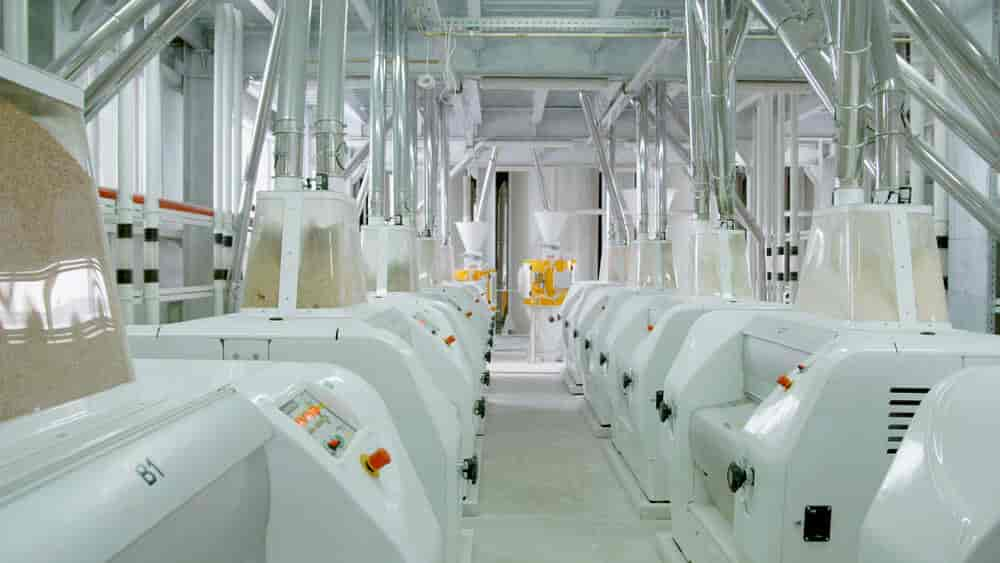
With the successful completion of the civil and mechanical work of the first flour section of the BFM project, FK Engineering is now moving into a critical new phase — the electrical services. This stage not only powers the infrastructure built so far but also ensures the seamless integration of all systems for operational excellence. The electrical setup is a cornerstone in the development of any industrial facility, and in the case of a flour mill, it plays a pivotal role in ensuring efficiency, safety, and automation.
This article provides an in-depth overview of FK Engineering’s approach, planning, and execution strategy for the electrical phase of the BFM first flour section project.
Importance of the Electrical Services / Setup in Flour Mill Operations
Electrical infrastructure is the lifeblood of a modern industrial Services. For a Complete flour mill Setup like BFM, it governs:
- Power supply to milling and conveying equipment
- Control and automation of machinery
- Safety systems including fire alarms and emergency shut-offs
- Lighting and HVAC systems
- Monitoring and data collection via SCADA or PLC systems
A well-executed electrical setup ensures uninterrupted operations, lower maintenance costs, and compliance with industry standards. FK Engineering recognizes the significance of this phase and is employing a meticulous and structured approach.
Electrical Design and Planning
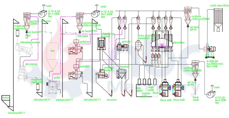
Before physical work begins, detailed planning and design are necessary. FK Engineering’s electrical team has developed:
1. Single-Line Diagrams (SLDs)
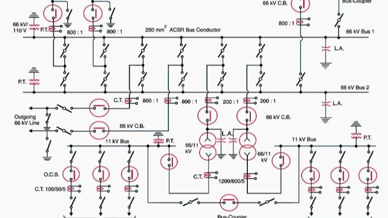
SLDs provide a simplified overview of the electrical distribution system — from main power entry to final load points. It includes transformers, main distribution panels (MDPs), sub-distribution panels (SDPs), and motor control centers (MCCs).
2. Load Calculations
Comprehensive load analysis has been conducted to calculate the total power requirement of the first flour section. This includes:
- Main milling machines
- Pneumatic conveyors
- Sifters and separators
- Elevators and gear motors
- Lighting and control systems
3. Cable Schedules and Routing
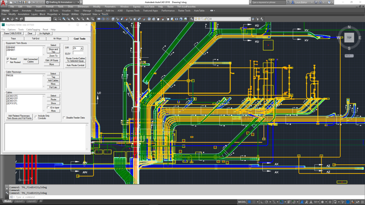
Proper cable sizing, insulation ratings, and routing paths have been determined based on load, distance, and environmental conditions within the plant.
4. Equipment Specification
FK Engineering has shortlisted high-quality components and switchgear from reputable suppliers to ensure longevity and efficiency. Brands like Schneider Electric, Siemens, and ABB are being considered.
Key Components of the Electrical Setup
1. Main Power Supply and Distribution
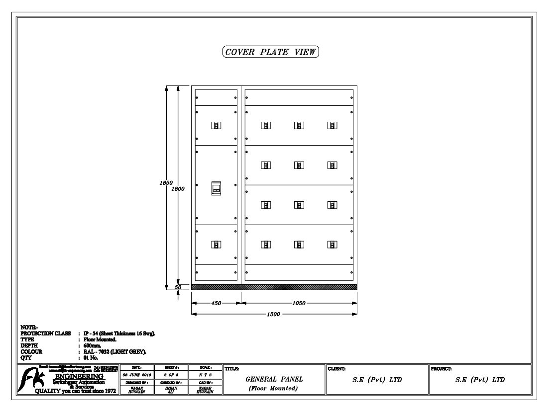
The electrical setup begins with the main power intake from the utility grid. A dedicated transformer is being installed to step down the voltage to the required operating level. From here, the power is routed to the main distribution panel (MDP).
Components involved:
- Step-down Transformer (e.g., 11kV/400V)
- Main Distribution Panel with circuit breakers and surge protection
- Automatic Transfer Switch (ATS) for backup power integration
- Capacitor banks for power factor correction
2. Motor Control Centers (MCCs)
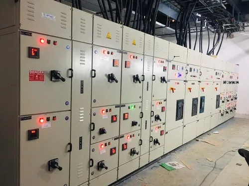
MCCs control and distribute power to the motors driving various flour mill machinery. They are equipped with:
- Direct-On-Line (DOL) and Star-Delta starters
- Variable Frequency Drives (VFDs) for speed control
- Overload relays and circuit breakers
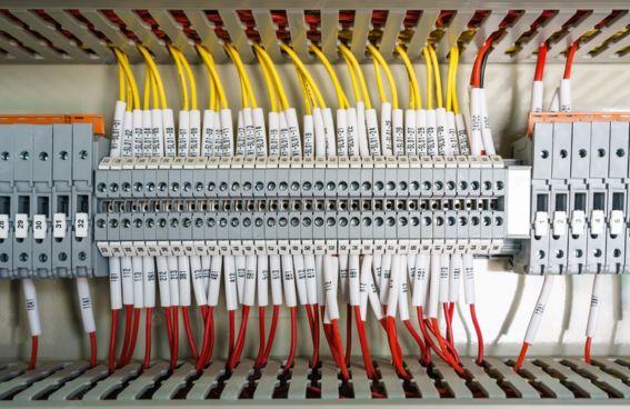
- Control and instrumentation terminals
This setup allows flexibility and energy efficiency, particularly in machines where speed regulation is critical.
3. Control Panels and PLC Integration
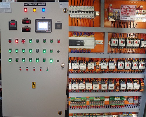
FK Engineering is implementing advanced automation through Programmable Logic Controllers (PLCs). This allows for:
- Automated operation of milling processes
- Real-time monitoring of motor status, temperature, and performance
- Interlock systems to prevent unsafe operations
- Data logging and diagnostics
Human Machine Interfaces (HMIs) will also be installed for operator interaction and process visualization.
4. Cabling and Trunking System
Electrical power and control cables will be laid through properly designed trays and trunking systems. Segregation of power and control cables is ensured to reduce electromagnetic interference (EMI).
Cable types include:
- XLPE-insulated power cables
- Multi-core shielded control cables
- Communication cables (e.g., CAT6 or fiber) for PLC networking
Cable trays will be galvanized and corrosion-resistant to suit the mill’s industrial environment.
5. Earthing and Lightning Protection
To ensure safety and compliance, a robust earthing system is being installed. Key features include:
- Earth pits and electrodes at critical points
- Equipotential bonding of all metallic structures
- Lightning arrestors at building tops
- Surge protection devices (SPDs) in panels
This ensures personnel safety and protects equipment from transient surges and lightning strikes.
6. Lighting and General Power
Factory lighting is being designed to ensure optimal illumination for operations and maintenance. The system includes:
- LED high-bay lights in processing areas
- Emergency lights in evacuation routes
- Outdoor floodlights and streetlights
- Socket outlets for portable tools and maintenance
All lighting will be energy-efficient and comply with industry lighting norms.
Project Execution Plan
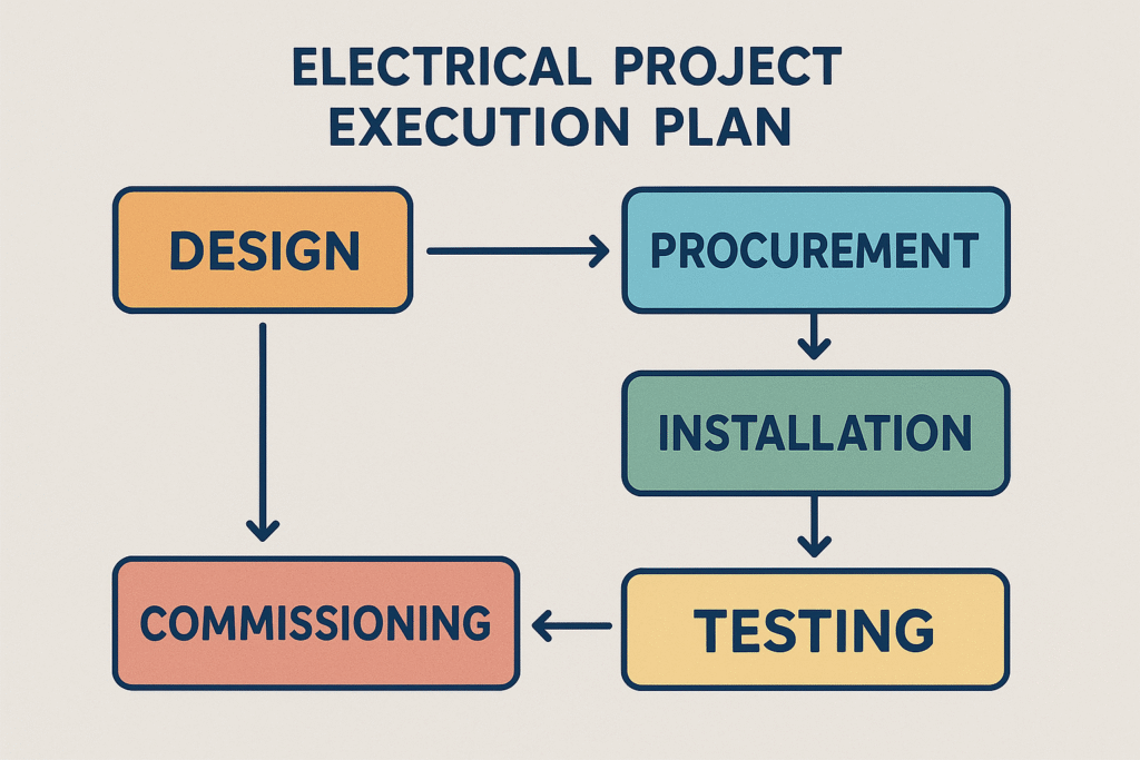
1. Site Preparation
The electrical team is currently conducting site surveys and marking trenches and routing paths for cables and conduits. Temporary power arrangements are already in place for construction activities.
2. Procurement and Pre-fabrication
Switchboards and panels are being fabricated off-site to maintain quality and save time. FK Engineering is coordinating with suppliers for timely delivery of electrical components.
3. Installation Phase
The installation will begin with:
- Transformer and main panel setup
- MCC installation near equipment clusters
- Cable laying and termination
- Earthing grid implementation
- Control panel mounting and wiring
FK Engineering will deploy skilled electricians under the supervision of qualified engineers to ensure compliance with electrical codes.
Each component will be tested for:
- Continuity and insulation resistance
- Voltage and load balancing
- Functional testing of motors and PLCs
- Verification of interlocks and safety systems
After successful dry testing, live testing will be carried out before handing over to operations.
Safety and Compliance
FK Engineering is strictly following national and international electrical safety standards such as:
- IEC and NEC standards
- Local electrical codes
- NFPA 70E for electrical safety in the workplace
All electricians and engineers are using PPE (Personal Protective Equipment), and Lockout-Tagout (LOTO) procedures are enforced for maintenance tasks.
Integration with Future Phases
This first electrical setup is designed with scalability in mind. Provisions are made in panels and control systems to integrate:
- Future production lines
- Additional storage silos
- Packaging and dispatch automation
- Energy monitoring systems
This forward-looking approach ensures the mill can expand without requiring a complete redesign of the electrical infrastructure.
Conclusion
The transition from civil and mechanical works to the electrical phase marks a major turning point in the development of BFM’s first flour section. FK Engineering’s meticulous planning, technical excellence, and focus on safety are setting the stage for a world-class flour production facility.
The electrical setup is not just about powering machines — it’s about enabling intelligent, efficient, and safe operations. FK Engineering is committed to delivering this phase with the same dedication and precision that characterized the earlier stages of the project.
As installation progresses, FK Engineering continues to uphold its reputation for quality, innovation, and client satisfaction — lighting the path forward for BFM’s industrial success.


